High-energy ion irradiation is an important tool for studying radiation damage effects
Materials in a nuclear reactor are exposed to extreme temperature and radiation conditions that degrade their physical properties to the point of failure. For example, alpha-decay in nuclear fuels results in dislocation damage to and accumulation of helium and fission gasses in the material.
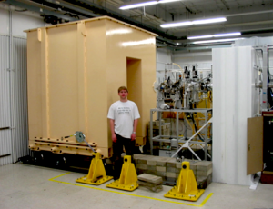
Similarly, neutrons interacting with non-nuclear components can displace atoms from the crystal lattice and create hydrogen and helium via nuclear reactions. These species, either individually or in concert, can induce physical changes to the microstructure of a material that can fundamentally alter its mechanical properties. Ion beams have been proven to be an effective means to simulate radiation damage effects and offer distinct advantage compared to reactor irradiations. A beamline has been constructed at CAMS [Figure. 1] that can be used for the irradiation of materials and has been applied to several important studies of radiation damage effects.
Mechanisms of phase degradation associated with dimensional instability in actinide fuels
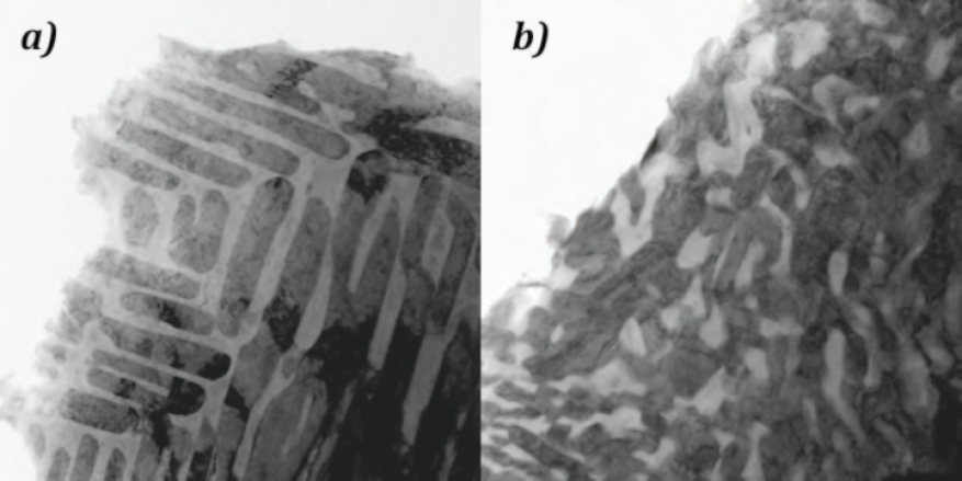
We have been involved in a research project aimed at understanding the radiation-induced effects on the phase stability of actinide fuel alloys. This project, led by materials scientists in the LLNL's Condensed Matter and Materials Division and in collaboration with Idaho National Laboratory, involved the fabrication and microstructural characterization of uranium-zirconium and uranium-molybdenum alloys. This work led to the discovery of the coexistence of two distinct alloy phases (alpha a delta) arranged in laminar, plate-like structures within the material [Figure. 2a]. Upon irradiation of these materials with heavy ions to produce dislocation damage, the two phases became less distinct with a noticeable degradation of the laminar structure. Understanding the mechanism behind this change in phase structure is critical to predicting the impact on dimensional stability of these alloys.
Accelerating the development of radiation tolerant materials
Another important application of our high-energy ion implantation capability is the study of radiation tolerant structural materials. One of the major challenges in designing future fusion reactors is the selection of suitable structural materials.
Materials that resist radiation damage effects (e.g., material hardening and embrittlement, dimensional instability caused by void- and helium-driven swelling, etc.) are necessary to maximize the lifetime and efficiency of the reactor. Oxide dispersion strengthened (ODS) steels, which are composed of high-strength ferritic martensitic steels in which oxide nano-particles are dispersed, are a class of materials that exhibit particularly high radiation tolerance. The specific mechanisms of how ODS steels resist radiation damage effects is of great interest to the fusion energy community.
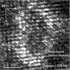
By applying our ion implantation capability, we can introduce displacement damage (via heavy ions), and transmutation products (e.g., He, H, etc.) into ODS samples several orders of magnitude quicker than is achievable in available test reactors.This significantly accelerated the investigation of unit mechanisms that are responsible for radiation-induced changes to the microstructure of materials. Figure 3 shows a high-resolution TEM image of an ODS steel irradiated with heavy ions and He.
The oxide nano-particles act as nucleation points for small helium bubbles that eventually agglomerate around the particle [Figure 4]. In non-ODS steels, these bubbles would fill cavities within the metal matrix created by displacement damage. These cavities eventually grow into voids that lead to dimensional instability in the material which causes degradation of mechanical properties. By trapping the helium bubbles, the oxide nanoparticles in ODS steels effectively prevent void growth and thus result in enhanced radiation tolerance.
Plutonium implantation
Plutonium samples have also been implanted with helium. The principal decay mechanism for most plutonium isotopes is alpha-particle decay. In this process, the parent atom spontaneously decays into a uranium atom with the emission of a doubly charged helium nucleus (i.e., alpha particle). The alpha decay of a plutonium isotope typically produces a helium ion that has an energy of 4.5 to 5.5 MeV, whereas, the recoil nucleus has an energy of 70 to 100 keV. The alpha particle creates little damage to the lattice; however, the U atom dislodges thousands of plutonium atoms from their normal positions in the crystal lattice, producing vacancies and interstitials known as Frenkel pairs. When an alpha particle stops in a solid, it becomes a helium atom. Consequently, alpha-particle decay ultimately leads to the formation of helium atoms resulting in aged plutonium material becoming enriched in helium and uranium. Positron annihilation experiments indicate that a newly formed helium atom immediately fills an unfilled vacancy. These helium-filled vacancies migrate in the lattice, eventually coalescing as helium bubbles.
One of the intriguing questions about plutonium as it decays is the evolution of helium bubbles. To shed light on He bubble size and evolution, plutonium samples containing up to one-atomic percent helium (equivalent to helium content resulting from approximately 250 years of alpha decay) have been fabricated via helium ion implantation.
Plutonium samples containing up to one-atomic percent helium, were fabricated using the high-energy helium ion implantation capability at CAMS. By sequentially lowering the helium ion energy in a well-defined manner, the depth of the implanted can be successively reduced, producing a plutonium sample with relatively uniform helium content over the implanted depth. He implants were conducted into a plutonium sample that had been rolled into a 105-micron thick wafer. The wafer was implanted with He2+beams of energy 16.96 followed by 16.21, 15.49, 14.78, 14.09, 13.42 and finally 12.75 MeV. Beam currents were ~ 1- 2 uA particle focused into a 5 mm diameter beam spot on target and the total irradiation took ~ 12 hours. The dosing profile was designed to produce a sample that would contain 1 atomic percent helium over a depth of 40 to 65 micron. Active cooling of the sample kept the average sample temperature at ~50°C during implantation and the maximum sample temperature was kept below ~110°C.
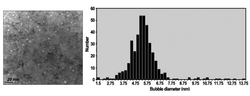
TEM analysis of the implanted sample (Figure 5) indicates that the bubble size appears to be approximately 1.5 nm (similar to that observed in 20 to 40 year old plutonium) and the visible bubble density is around 3 x 10¹⁷ /CC (compared to 2x 10¹⁷ /CC in 40 year old plutonium) indicating that the helium bubble evolution may be governed by the same processes whether He is produced by decay or by implantation.

